Knowing how to install forklift warning lights correctly is often the only barrier between a safe, compliant worksite and costly operational downtime or OSHA violations. A rushed installation, a poorly aimed beam, or an incorrect wiring connection doesn’t just look unprofessional—it creates a false sense of security that puts pedestrians at risk. When a vital safety device fails intermittently due to a loose connector or the wrong fuse, it becomes an unpredictable liability for your entire operation.
This guide provides a definitive technical procedure for getting the job done right the first time. We will cover choosing the optimal mounting locations for front, rear, and side lights to eliminate blind spots. Then, we’ll move into a detailed, step-by-step wiring process that addresses proper voltage, relays, fuses, and connectors. You’ll also learn how to aim and test each light for maximum visibility and avoid the common installation mistakes that lead to premature failure and compliance issues.
Why Correct Forklift Warning Light Installation Matters
Proper installation directly reduces accidents and protects equipment, ensuring warning systems function as a reliable safety asset rather than a liability.
Preventing Collisions in High-Risk Zones
Correctly installed warning lights create a tangible buffer zone around moving equipment. A rear-mounted blue spotlight projects a clear beam 10 to 20 feet behind a reversing forklift, giving pedestrians critical advance warning to react and avoid a collision. In tandem, forward-mounted red lights define a distinct “no-go zone” on the floor, visually instructing staff to maintain a safe distance. This strategy is most effective at eliminating visibility gaps in high-risk areas like blind intersections, crowded loading docks, and narrow warehouse aisles where an operator’s line of sight is obstructed.
Enhancing Pedestrian Awareness and Regulatory Compliance
In loud industrial environments, audible alarms are often ineffective. Projected light beams provide a silent but highly visible alert that bypasses auditory distractions from machinery or personal audio devices. Mounting these lights on the forklift’s overhead guard elevates the beam source, creating a highly visible and unambiguous safety perimeter on the floor below. This not only improves on-the-ground awareness but also demonstrates a commitment to safety standards, helping meet OSHA requirements and protecting the business from potential fines and legal liabilities tied to workplace accidents.
Improving Operational Precision and Equipment Longevity
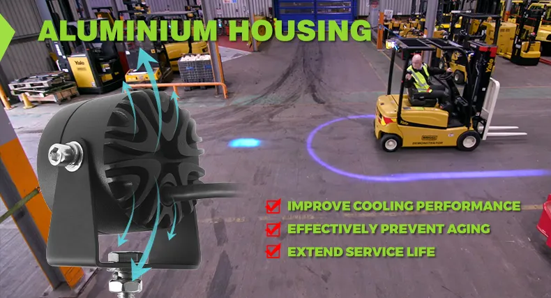
Beyond pedestrian safety, properly aimed lights serve as a valuable tool for the operator. The projected beams can act as a guide for accurate fork and load positioning, reducing the risk of accidental damage to expensive pallets and racking infrastructure. The physical installation is just as critical for the hardware itself. A stable, secure mounting protects the light from operational shock and vibration. This ensures the LED system achieves its full 30,000-hour rated service life, maximizing the return on investment and minimizing downtime for repairs or replacements.
Types of Forklift Warning Lights and Power Requirements
Matching the correct warning light type to its intended function and ensuring power system compatibility are fundamental to a reliable and effective forklift safety protocol.
Red and Blue LED Safety Zone Lights
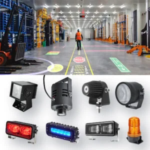
Zone lights establish a clear visual perimeter around the equipment to prevent pedestrian collisions. Red zone lights project a distinct red line on the floor alongside the forklift, creating a visible “no-go zone” that alerts workers to maintain a safe distance from the sides, which is especially critical during turns. Blue LED spotlights are typically mounted on the rear overhead guard to project a concentrated beam on the floor 10 to 20 feet behind the reversing vehicle. This combination provides a comprehensive safety halo, giving pedestrians a direct visual cue of the forklift’s proximity and direction of travel, particularly at blind intersections and in loud environments where audio alarms are ineffective.
Strobe and Flashing Beacon Lights
Strobe and beacon lights serve as a primary, general alert for vehicle presence. Unlike directional zone lights, these devices emit high-intensity flashes to provide a 360-degree visual warning that cuts through ambient noise and distraction. Mounting them on the forklift’s overhead guard or mast ensures maximum visibility from all angles and distances. Their function is not to define a specific safety zone but to signal that a forklift is active in the area, making them a critical component for operations in busy or poorly lit warehouses.
Voltage Compatibility and Durability Specs
For any warning light to perform reliably, it must match the forklift’s electrical system and withstand the industrial environment. Key technical specifications include:
- Voltage Range: Modern LED lights are engineered to operate across a wide voltage range, typically 10-80V DC, ensuring they can integrate directly with the electrical systems of various forklift makes and models without modification.
- Power Consumption: High-efficiency LED chips draw minimal power from the forklift’s battery. This low-amperage design prevents significant drain on the vehicle’s power supply, allowing for extended operational shifts without compromising performance.
- Durability Rating: A housing with an IP67 or IP68 rating is essential. This certifies the unit is fully sealed against dust ingress and can endure immersion in water, making it resilient to high-pressure washing, impacts, and harsh weather conditions.
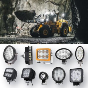
Boost Productivity with Rugged LED Work Lights
Best Mounting Locations for Front, Rear, and Side Warning Lights
Strategic light placement is non-negotiable for creating a complete visual safety perimeter and preventing accidents in high-risk areas like aisles and intersections.
Front Mounting for Forward Movement and Intersection Safety
Positioning red spotlights on the forklift’s overhead guard projects a clear “no-go zone” in front of the moving vehicle. This placement is essential for providing advance warning to pedestrians, especially at blind corners and busy aisle intersections where an operator’s view may be obstructed. The projected light beam also serves a dual purpose by helping operators position the forks with greater accuracy, which reduces accidental damage to pallets and warehouse racking during loading operations.
Rear Mounting for Reversing and Pedestrian Awareness
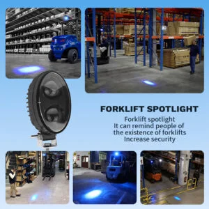
Installing a blue LED safety light on the rear of the forklift frame is a standard industry practice for signaling reversing maneuvers. The light projects a focused, moving beam on the floor 10 to 20 feet behind the equipment. This visual alert is highly effective in noisy environments where audible alarms might be missed by distracted or hearing-impaired workers. While not explicitly mandated by OSHA, this type of visual warning system aligns with safety best practices for providing a distinct alert for backward movement.
Side Mounting to Establish a Complete Safety Perimeter
Placing red-line warning lights along the sides of the overhead guard creates a continuous visual boundary, effectively marking the forklift’s complete operational footprint. This “red zone” clearly defines a safe distance for adjacent workers, which is critical in narrow aisles or congested areas. By illuminating the full swing radius of the rear end, these side-mounted lights help prevent collisions caused by the forklift turning in tight spaces.
Step-by-Step Wiring Guide: Voltage, Relays, Fuses, and Connectors
Proper wiring ensures operational reliability, protects LED components from voltage spikes, and prevents electrical failures that can sideline essential equipment.
Pre-Wiring Checklist and Safety Protocols
Before starting, a systematic check prevents common installation errors. First, use a multimeter to confirm the vehicle’s system voltage—typically 12V or 24V—matches the lamp’s specifications to avoid damage. As a mandatory safety step, disconnect the battery’s negative terminal to eliminate the risk of short circuits. Finally, gather the necessary tools: a multimeter, wire strippers, terminal crimpers, and the appropriate 18 AWG wiring to handle the current draw.
Mapping the Circuit from Power Source to Lamp
A well-planned circuit is the foundation for a durable installation. Identify a fused, switched power source capable of handling the lamp’s electrical load without overloading the vehicle’s existing circuits. Plan a secure wire path that avoids high-heat engine components, sharp metal edges, and moving parts to prevent chafing and insulation failure.
Installing the Relay for High-Current Loads
High-output LED lamps require a relay to manage the electrical current safely, protecting the operator’s switch from overheating and failure. Mount the relay in a dry, secure location shielded from moisture and heavy vibration. Connect the low-current control circuit from the operator switch to relay pins 85 and 86. Run the high-current power wire from the fused battery source to pin 30. The final connection runs from pin 87 directly to the lamp’s positive terminal, delivering the stable power required for peak performance.
Selecting and Placing the Correct Fuse
The fuse is the circuit’s primary safety device. Calculate the required amperage by dividing the lamp’s total wattage by the system voltage (e.g., 36W / 12V = 3A), then add a 25% safety margin. This calculation typically specifies a 5-amp fuse for standard LED warning lights. Install the in-line fuse holder on the positive wire as close to the battery terminal as possible. This placement ensures the entire length of the new wiring is protected from a short circuit. Never substitute a higher-rated fuse, as doing so creates a fire risk.
Securing Terminals with Weatherproof Connectors
Forklift operating environments demand robust connections that resist vibration and contaminants. Use the provided IP67-rated connectors for all external wiring to create a sealed, reliable electrical path. A solid connection is both mechanical and electrical; strip each wire to the correct length and crimp it firmly to the terminal pin. For any non-sealed connections, apply heat shrink tubing over the terminal to add insulation, provide strain relief, and protect against corrosion.
Final System Test and Voltage Verification
Once all connections are secured, perform a final system verification before returning the equipment to service. This check confirms the system is performing to specification and prevents unexpected failures.
- Reconnect the battery’s negative terminal.
- With the circuit off, use a multimeter to check for continuity and confirm no short-to-ground fault exists in the new wiring.
- Activate the switch and measure the voltage directly at the lamp’s connector to verify it is within the operational range and there is no significant voltage drop.
Aiming and Testing Warning Lights for Maximum Visibility

Precise beam alignment and functional testing are non-negotiable steps that transform a warning light from a simple accessory into a reliable collision prevention system.
Establishing the Visual Safety Perimeter
A correctly configured warning light system creates a clear visual boundary. Project the main beam 10 to 20 feet from the vehicle to establish a definitive ‘no-go zone’ for pedestrians, giving them sufficient reaction time in high-traffic environments. This simple color-coding ensures that the projected beam offers advance warning before the vehicle enters an aisle or intersection.
Calibrating Beam Alignment in Critical Zones
Beam diffusion reduces a light’s effectiveness. Adjust the light’s angle to project a focused, intense spot on the ground, preventing the warning signal from getting lost in narrow aisles or at busy intersections. Lights mounted on the overhead guard should be aimed to maximize ground coverage around the forklift’s base. To account for blind spots, angle the beams so the light is visible on the floor *before* the forklift itself emerges from a corner, giving pedestrians the earliest possible alert.
Conducting Functional Visibility Tests
After aiming the lights, a series of functional tests confirms their real-world performance. This step verifies that the light is not just working but working correctly in your specific environment.
- Perform a complete walk-around inspection, viewing the projected beam from multiple angles and distances to confirm consistent visibility.
- Test the beam’s effectiveness in both brightly lit warehouse sections and dimly lit operational areas, like loading docks or outdoor spaces at dusk.
- Verify that the projected light maintains its intensity and shape at the target distance, meeting the safety requirements outlined by OSHA and your facility’s protocols.
Common Installation Mistakes and How to Avoid Them
Proper installation is non-negotiable; even premium lights fail if they are poorly aimed, wired, or mounted, directly compromising worksite safety and operational uptime.
Incorrect Beam Alignment and Positioning
A common failure is improper beam aiming. The light must project a clear warning spot on the floor 10 to 20 feet away from the forklift to give pedestrians adequate reaction time. Aiming the beam too close or too far renders it ineffective. Another critical error is reversing light placement; the industry standard is red lights for the front perimeter and blue lights for the rear to indicate the direction of travel. Misaligning the beam also creates dangerous blind spots, leaving high-risk areas like intersections and narrow aisles unprotected where operators have limited visibility.
Improper Wiring and Electrical Connections
Electrical mistakes introduce immediate points of failure. Technicians sometimes bypass the supplied wiring harness, which can lead to voltage mismatches with the forklift’s 48V+ system or trigger CANBUS errors. Even with the correct harness, insecure connections will inevitably loosen from constant operational vibration, causing intermittent light failure. The most damaging error is compromising the wire’s insulation during installation. This exposes the internal wiring to moisture and debris, creating a direct path for short circuits that can disable the light or, in worst-case scenarios, cause high-current arcing.
Final Installation Checklist
This final verification process ensures every light functions correctly under operational stress, directly preventing installation errors that compromise warehouse safety and compliance.
Verify Beam Alignment and Projection Distance
Proper beam placement is non-negotiable for effective pedestrian warning. The goal is to create unambiguous visual cues that are consistent across the entire fleet. Misalignment renders the system useless and can create a false sense of security.
Conduct Power-On and System Function Test
The final step is a live systems test to simulate real-world use. This check validates the electrical connections, light performance in varied conditions, and system compatibility with the forklift’s onboard electronics.
- Instant Illumination: Power on the forklift. All warning lights must illuminate immediately without any flickering, delay, or dimming. Test any switches to ensure they activate the lights as intended (e.g., connected to reverse alarms or ignition).
- Environmental Visibility Test: Operate the forklift in both brightly lit areas and dimly lit warehouse sections. The projected beams must remain clearly visible and distinct on the floor surface in all typical ambient lighting conditions.
- System Compatibility: Check the forklift’s dashboard for any error codes or fault indicators. The absence of errors confirms the new lights are fully compatible with the vehicle’s CANBUS system and are not creating electrical conflicts.
Conclusion
Skipping professional installation or using non-certified lights exposes your fleet to higher failure rates, compliance risks, and significant liability costs. Sourcing industrial-grade hardware, like lights built with OSRAM LEDs and IP68-rated aluminum housings, is a direct investment in operational uptime. This level of quality control is no longer optional; it is the standard for protecting your assets and reputation.
Your next step is to validate this standard for your own fleet. Request a sample kit to test our hardware’s durability and brightness firsthand. We can also provide the complete forklift lighting catalog or schedule an OEM consultation to discuss your specific technical needs.
Frequently Asked Questions
What are the zone warning lights for forklifts?
Forklift zone warning lights are visual safety devices that create a “no-go zone” or safety perimeter around the equipment. Typically, these include red spotlight lights installed on the front or overhead guard and blue LED lights on the back. This system establishes a clearly visible boundary to warn pedestrians to maintain a safe distance and prevent collisions, especially in narrow aisles and at blind intersections.
What are the three types of warning signs?
Based on the provided research, forklifts use three primary types of warning systems: 1) Red zone lights, which are often mounted on the overhead guard to create a safety perimeter. 2) Blue safety lights, typically mounted on the rear to warn of reversing equipment by projecting a beam 10 to 20 feet away. 3) Traditional auditory warnings like horns, which are supplemented by visual lights to be more effective in noisy environments or when workers are distracted.